The proper size of the rotary actuator is critical in pneumatic automation.
An undersized actuator may stall, wear, or fail under maximum load conditions, while an oversized actuator results in wasted compressed air, increased system costs, and expanded space requirements.
This engineering guide aims to teach the reader the right way to properly size a pneumatic rotary actuator, including the correct way to calculate the required torque, the correct pressure to use, inertia analysis, and application considerations.
Quick Answer: How to Size a Rotary Actuator?
To size a pneumatic rotary actuator:
- Calculate required torque (static + friction + inertia)
- Apply a 25–50% safety factor
- Use minimum supply pressure for torque rating
- Account for valve breakaway torque (if applicable)
- Match actuator torque curve to operating conditions
- Verify mounting interface and shaft load capacity
Proper rotary actuator sizing ensures stable torque output, longer service life, and lower total cost of ownership.
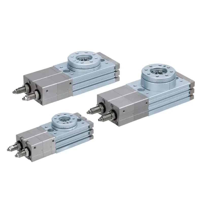
What Is a Pneumatic Rotary Actuator?
A pneumatic rotary actuator converts compressed air energy into limited-angle rotational motion — typically 90°, 180°, or custom angles.
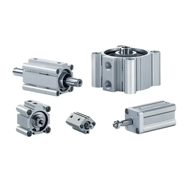
Common internal mechanisms include:
- Rack and pinion rotary actuator
- Vane type rotary actuator
- Helical spline rotary actuator
- Scotch yoke (heavy-duty torque applications)
Typical applications:
- Ball valve and butterfly valve automation
- Indexing systems
- Clamping devices
- Robotic end-of-arm tooling
- Packaging and assembly machinery
In industrial automation, rotary motion control is essential for repeatable angular positioning and valve control systems.
Step-by-Step: Pneumatic Rotary Actuator Sizing Method
Step 1: Calculate Required Torque
The basic static torque formula:
T = F × r
Where:
T = Torque (Nm)
F = Applied force (N)
r = Lever arm length (m)
This formula applies to static loading conditions.
Example: Static Torque Calculation
If:
Load force = 300 N
Lever arm = 0.1 m
T = 300 × 0.1 = 30 Nm
Apply safety factor (30%):
T_design = 30 × 1.3 = 39 Nm
Final required torque ≈ 40 Nm
Important: Include All Torque Components
For real industrial systems, total required torque is:
Total Torque =
Static Torque
- Friction Torque
- Inertia Torque
- Safety Margin
Many actuator failures occur because only static torque was considered.
Step 2: Account for Inertia (Often Ignored)
For high-speed indexing or fast valve actuation, inertia matters.
Inertia torque:
T = J × α
Where:
J = Moment of inertia (kg·m²)
α = Angular acceleration (rad/s²)
Angular acceleration:
α = Δω / Δt
If rotation must occur quickly, acceleration torque can significantly increase total torque requirement.
In real installations, actuators that look sufficient on paper often fail during rapid cycling because inertia torque was underestimated.
Step 3: Size Based on Minimum Supply Pressure
Pneumatic rotary actuator torque output is proportional to air pressure.
Approximate relationship:
T_actual = T_rated × (P_actual / P_rated)
If rated torque is given at 0.6 MPa:
And your system minimum pressure is 0.5 MPa:
Actual torque = 45 × (0.5 / 0.6) = 37.5 Nm
Always use the minimum guaranteed operating pressure, not the maximum compressor rating.
Pressure fluctuations, long air lines, and regulator losses must be considered.
Step 4: Consider Valve Breakaway Torque
For valve automation:
Breakaway torque > Running torque
Always use the highest torque value specified by the valve manufacturer at maximum differential pressure.
For critical valve systems, a 50% safety factor is recommended.
Example: Sizing a Rotary Actuator for a Ball Valve
Application:
DN50 ball valve
Breakaway torque = 28 Nm
Minimum air pressure = 5 bar
Add 50% safety margin:
28 × 1.5 = 42 Nm
Select actuator rated ≥ 42 Nm at 5 bar.
If torque chart shows:
45 Nm at 6 bar
Then at 5 bar:
45 × (5 / 6) = 37.5 Nm → Not sufficient
Next larger model must be selected.
This step prevents undersizing errors common in valve automation projects.
Choosing the Right Type of Rotary Actuator
Rack and Pinion Rotary Actuator
- High torque output
- Compact structure
- Ideal for 90° valve automation
- Cost-effective
- Most common in industrial systems
Vane Type Rotary Actuator
- Smooth rotation
- Simple structure
- Lower torque range
- Suitable for light-duty positioning
Helical Rotary Actuator
- High torque density
- Good repeatability
- Suitable for precision indexing
Technical Parameters to Compare
When selecting a pneumatic rotary actuator, compare:
- Rated torque at 0.6 MPa
- Torque curve vs pressure
- Rotation angle (90° / 180° / adjustable)
- Repeatability (±0.5° typical)
- Maximum operating pressure
- Shaft radial load capacity
- Cushioning system
- ISO 5211 mounting standard (for valves)
- Duty cycle rating
Never select based only on physical size.
Common Rotary Actuator Sizing Mistakes
- Ignoring inertia torque
- Using maximum pressure instead of minimum
- Not applying safety factor
- Overlooking valve breakaway torque
- Ignoring air supply pressure drop
- Selecting actuator only by flange size
Proper engineering analysis prevents early failure and unstable motion.
Pneumatic vs Electric Rotary Actuators
Feature | Pneumatic | Electric
Speed | Very fast | Moderate
Cost | Lower | Higher
Precision | Moderate | High
Explosion-proof | Excellent | Requires special design
Maintenance | Simple | Electronic components involved
Pneumatic rotary actuators remain ideal for:
- Hazardous environments
- High-cycle industrial automation
- Cost-sensitive OEM machinery
FAQ
Typically 25–50%.
For valve automation: 50% recommended.
Yes, but oversizing increases air consumption and may cause impact at end stops if not properly cushioned.
Use manufacturer breakaway torque at maximum pressure differential.
For ±0.5° to ±1° repeatability, yes.
For servo-level positioning, electric actuators are preferred.
Need Help Sizing a Rotary Actuator?
If you provide:
- Required torque (or valve model)
- Minimum supply pressure
- Rotation angle
- Application type
- Required cycle speed
CHDAC engineering team can recommend a suitable pneumatic rotary actuator model and provide torque curve data.
We support:
- ISO standard rack and pinion rotary actuators
- Adjustable stop versions
- Magnetic position sensing
- Stainless steel versions
- OEM customization for automation equipment manufacturers
With extensive experience in pneumatic component manufacturing, CHDAC supports automation OEMs with stable torque performance, consistent quality, and application-focused engineering support.
Final Thoughts
Sizing a rotary actuator correctly is not simply choosing a torque value from a catalog.
It requires:
- Accurate torque calculation
- Pressure-based verification
- Inertia consideration
- Safety margin application
- Application-specific evaluation
Proper rotary actuator sizing ensures:
- Reliable valve control
- Stable indexing motion
- Reduced downtime
- Lower total operating cost
For industrial automation systems, working with an experienced pneumatic manufacturer ensures both correct selection and long-term reliability.
CHDAC – Pneumatic Components for Reliable Industrial Automation